
Complete Guide to Container Corner Casting Types: ISO 1161 Classifications, Materials, and Applications
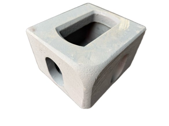
Corner Castings are the standardized cast-steel blocks positioned at all eight corners of an ISO shipping container. They are the single most critical structural component in global container logistics — every crane lift, every stack, every chassis lock, and every lashing rod passes its forces through these precisely engineered fittings. This guide catalogues every recognized corner casting type, from position-based classifications to material variants and non-standard international specifications.
What Are Container Corner Castings and Why Do They Matter?
Every standard ISO shipping container — whether a 20-foot dry van crossing the Pacific or a 40-foot high-cube refrigerated unit hauling pharmaceuticals across Europe — is built around a steel frame whose eight corners are terminated by identical-looking but carefully differentiated blocks called corner castings (also known as corner fittings, corner blocks, or ISO corner connectors). These castings are not generic brackets; they are load-bearing structural nodes engineered to millimeter tolerances, governed by the international standard ISO 1161, and certified by classification societies such as Lloyd’s Register, Bureau Veritas, DNV GL, ABS, and CCS.
The fundamental job of a corner casting is deceptively simple: provide a universal interface between the container and every piece of handling equipment in the world. A crane spreader in Shanghai locks into the same top-corner apertures as a reach stacker in Rotterdam. A twistlock on a container ship secures a bottom corner casting in exactly the same way whether the ship is registered in Panama, Singapore, or Liberia. This interchangeability is what makes the global container fleet work — and it rests on the precise dimensional and strength specifications of ISO 1161:2016.

The Scale of the Standard
There are approximately 40 million ISO shipping containers in active circulation worldwide. Each container carries eight corner castings, meaning roughly 320 million corner castings are currently in service across the globe. An estimated 5–7 million new corner castings are manufactured annually to supply new container builds and replacement demand. Every one of these components must meet the same standard, regardless of whether it was cast in China, India, or Eastern Europe.
The importance of corner casting types goes beyond simple compatibility. Selection of the wrong casting type — using a bottom casting in a top position, or fitting a standard ISO casting to an 8-foot-6-inch-wide USA inland container — can cause twistlock jams, crane spreader misalignment, structural overload, and in the worst case, catastrophic stack collapse.
How Are Corner Casting Types Classified by Position?
The most fundamental classification of container corner casting types is by position. Every ISO Series 1 freight container uses exactly eight corner castings arranged at the four top corners and four bottom corners of the frame. But these eight castings are not interchangeable — each corner requires a specific type, and installing the wrong one compromises the container’s handling compatibility.
The Eight-Corner Layout
Stand at either end of a shipping container, facing the door or the front wall. The four corners you see — two at the top edge and two at the bottom edge — contain the following corner casting types:
- Top Left (TL) — upper corner on the left side from the viewer’s perspective
- Top Right (TR) — upper corner on the right side
- Bottom Left (BL) — lower corner on the left side
- Bottom Right (BR) — lower corner on the right side
The opposite end of the container mirrors this arrangement. The full complement per container is therefore: 2 × TL, 2 × TR, 2 × BL, 2 × BR.
Below is a summary of the four position-based types:
| Position Type | Quantity per Container | Location | Identifying Marks |
|---|---|---|---|
| Top Left (TL) | 2 | Upper corners, left side when facing either end | Stamped “TL” inside stacking hole |
| Top Right (TR) | 2 | Upper corners, right side when facing either end | Stamped “TR” inside stacking hole |
| Bottom Left (BL) | 2 | Lower corners, left side when facing either end | Stamped “BL” inside stacking hole |
| Bottom Right (BR) | 2 | Lower corners, right side when facing either end | Stamped “BR” inside stacking hole |
How to Read Casting Markings
Every certified ISO 1161 corner casting carries identification marks cast or stamped into the steel. The most useful for position identification are the two-letter codes — TL, TR, BL, BR — which are typically visible when looking through the main stacking hole into the internal cavity of the casting. These marks are cast during manufacturing and are permanent. If you are unsure which casting you are holding, peer through the large circular/elongated aperture on the top (for an upper casting) or bottom (for a lower casting) face and you will see the code on the internal wall.
Additional markings may include the manufacturer’s identification code, the casting heat number (for material traceability), and the classification society approval stamp (such as “LR” for Lloyd’s Register or “BV” for Bureau Veritas). These markings are essential during container inspection, repair, and certification renewal under the International Convention for Safe Containers (CSC).
Why Mirror Symmetry Matters
The left and right variants — TL vs TR, BL vs BR — are mirror images of each other. Their hole patterns, internal geometry, and external contours are reversed. While a TL casting and a TR casting appear nearly identical when held side by side, their apertures face outward in opposite directions once welded into the container frame. Fitting a TL casting to a TR position would orient the side apertures toward the container interior rather than the exterior, rendering the corner unusable for bridge clamps, lashing rods, or spreader engagement.
What Is the Difference Between Top and Bottom Corner Castings?
The distinction between top (upper) and bottom (lower) corner castings is the most significant classification difference within the ISO 1161 standard. Although both share the same external envelope — 178 mm × 162 mm × 118 mm — their apertures, internal geometry, and functional roles differ substantially.
Top Corner Castings: Anatomy and Function
Top corner castings serve as the primary lifting interface. When a crane or reach stacker picks up a container, the spreader locks into the four top corner castings. The top face of every upper casting features a large aperture — typically approximately 51 mm in diameter, though the exact shape can be round or slightly elongated depending on the manufacturer — which receives the twistlock cone or stacking pin.
On the side faces, the top casting has two distinct apertures:
- Long side (facing the container side wall): A stadium-shaped oval hole, approximately 65 mm × 130 mm, used for horizontal connection fittings (bridge clamps) and lashing accessories.
- Short side (facing the container end, door or front): An acorn-shaped (shield-shaped, also called keyhole or pear-shaped) hole, designed to accommodate crane spreader alignment pins and provide clearance for the spreader’s mechanical arms. This shield shape is the definitive visual marker of a top corner casting.
The top face aperture is the primary stacking and lifting hole. When containers are stacked, the twistlock or stacking cone of the container above passes through this hole and engages the internal locking surface.
Bottom Corner Castings: Anatomy and Function
Bottom corner castings handle vertical stacking loads from below — they sit on the twistlocks of the container beneath them, or on the chassis pins of a truck or railcar. The bottom face contains the stacking aperture (same approximate 51 mm diameter as the top).
On the side faces, bottom castings differ visibly from top castings:
- Long side: A stadium-shaped oval hole, identical in function to the top casting — used for bridge clamps and horizontal connections.
- Short side: Also a stadium-shaped oval hole — not the shield/acorn shape found on the top casting. This is the fastest visual identification: if the short-end hole is oval/stadium rather than shield-shaped, it is a bottom casting.
Additionally, many bottom corner castings incorporate small drain holes to allow water to escape, preventing internal corrosion and ice accumulation. These drains are absent on top castings because water would simply drain through the top aperture.
Side-by-Side Comparison
| Feature | Top Corner Casting (TL/TR) | Bottom Corner Casting (BL/BR) |
|---|---|---|
| Stacking hole location | Top face | Bottom face |
| Short-side hole shape | Shield / acorn (keyhole) | Oval / stadium |
| Long-side hole shape | Oval / stadium | Oval / stadium |
| Drain holes | None | Often present |
| Primary function | Lifting interface, stack top connection | Stack bottom connection, chassis lock |
| Typical weight | ~10.5–11.5 kg | ~10.5–11.5 kg |
| Visual identifier | Shield-shaped side hole | Only stadium/oval side holes |
The engineering reason for this differentiation is straightforward: crane spreaders rely on the shield-shaped hole on the container end for rapid guide-pin alignment. The spreader descends, its guide pins find the acorn holes on the two top castings at one end, and the twistlock mechanisms engage the top apertures. This would not function with the narrower oval holes found on bottom castings. Conversely, bottom castings do not need the shield shape because they interface from below with the twistlock cone, not from above with a spreader alignment system.
What Are the Different Hole Shapes in Corner Castings and What Do They Do?
Every ISO 1161 corner casting features three apertures, one on each outward-facing surface. These holes are not arbitrary — their shapes, dimensions, and positions are specified in ISO 1161:2016 to tolerances of ±1.0 mm to ±1.5 mm.
The Three Aperture Types
| Aperture Type | Shape | Approximate Dimensions | ISO 1161 Tolerance | Primary Function |
|---|---|---|---|---|
| Stacking hole (top/bottom face) | Round or slightly elongated | Ø ≈ 51 mm (internal access) | ±1.0 mm | Twistlock engagement, stacking cone insertion, crane lifting |
| Long-side hole | Oval / stadium | ~65 mm × 130 mm | ±1.5 mm | Bridge clamps, horizontal container joining, lashing rods, accessory mounting |
| Short-side hole (end face) | Shield / acorn (top castings only) or Oval / stadium (bottom castings) | ~65 mm × 130 mm (oval); shield varies by manufacturer | ±1.5 mm | Spreader guide-pin alignment (top), lashing and securing (bottom) |
Stacking Hole: The Load-Bearing Core
The stacking hole is the aperture through which all vertical forces pass. When a fully loaded 40-foot container — weighing up to 30,480 kg (67,200 lbs) — is lifted, the entire load is suspended through four stacking holes. When nine containers are stacked on a ship, the bottom corner castings of the lowest container bear a cumulative compressive load approaching 500 kN through their stacking holes.
The internal geometry of the stacking hole includes a machined landing surface that the twistlock cone or stacking pin bears against. This surface must remain flat and within dimensional tolerance; wear beyond 1–2 mm can cause uneven load distribution and accelerate fatigue cracking.
Stadium Holes: Horizontal Versatility
The stadium-shaped oval holes on the long side of every corner casting — and on the short side of bottom castings — provide the interface for horizontal connections between adjacent containers (bridge clamps) and for securing containers to ships, trains, and trucks using lashing rods, chains, or tensioning bars.
The approximate 65 mm × 130 mm opening is large enough to accept a variety of standardized fittings, including the rotating clamping plate of a Domino Clamp or similar container attachment bracket. The wall thickness around the stadium hole is critical: on genuine ISO 1161 castings, this measures approximately 19 mm (3/4 inch). Thinner walls indicate a non-ISO or lightweight fitting that may not meet load requirements.
Shield / Acorn Holes: The Spreader’s Guide
The shield-shaped hole — sometimes called acorn, keyhole, or pear-shaped — is the definitive feature of a top corner casting. Its wider upper section and narrower lower section create a funnel geometry that guides the crane spreader’s alignment pins during rapid loading operations. When a spreader descends at speed onto a container stack, the operator does not have time for millimeter-level precision; the shield shape accommodates a margin of positioning error and channels the pin into the correct engagement position.
This feature is found only on the short-side (end-face) aperture of top corner castings. Bottom castings do not carry shield holes because no spreader alignment interface is needed from below.
What Materials Are Corner Castings Made From, and How Do They Compare?
The overwhelming majority of container corner castings worldwide are manufactured from high-strength cast steel. However, specialized applications call for alternative materials, including stainless steel and aluminum. Understanding the material classification of corner casting types is essential for selecting the right product for corrosive environments, temperature extremes, or weight-sensitive applications.
Cast Steel: The Industry Standard
Cast steel corner fittings are produced from low-alloy carbon-manganese steels designed for excellent weldability, high toughness, and reliable mechanical performance across a temperature range of −40 °C to +70 °C. Common grades include:
- SCW480 (JIS standard): Minimum tensile strength of 480 MPa; widely used in Asian container manufacturing; excellent fatigue resistance.
- SCW490 (JIS standard): Higher tensile strength variant (490 MPa minimum); improved impact toughness for heavy-duty and offshore applications.
- ASTM A27 Grade 70-36: The North American equivalent; specified by Sea Box, Chassis King, and other US-based suppliers; tensile strength 485 MPa minimum, yield strength 250 MPa minimum.
The cast steel used for corner castings is typically not alloyed — it contains only iron, carbon (0.20–0.30%), manganese (0.60–1.00%), and silicon (0.30–0.60%). This composition ensures excellent machinability and, critically, weldability to the container frame. The corner casting itself must never be welded for repair purposes, but it must weld cleanly during original container assembly.
Some manufacturers offer corner castings in Corten steel (weathering steel), which develops a stable rust-like patina that inhibits further corrosion. This is the same material used for container side panels and provides extended service life in marine environments without paint coatings.
Stainless Steel: Corrosion-Specialist Applications
Stainless steel corner castings — typically grades 304 (A2) or 316 (A4) — are specified for containers operating in highly corrosive environments: chemical tank containers, food-grade tankers requiring washdown compatibility, offshore containers exposed to salt spray, and pharmaceutical logistics where corrosion by-products could contaminate cargo.
Stainless corner castings carry a significant cost premium (typically 2–4× the price of cast steel) and weigh approximately the same as their steel counterparts. They are available from specialized suppliers and are less commonly stocked than standard steel types.
Aluminum: Lightweight and Specialized
Aluminum corner fittings serve a narrow but important niche. They are primarily specified for:
- Military shelter containers: Where weight reduction is critical for air transportability
- Lightweight tank and bulker containers: Where reduced tare weight increases payload capacity
- Special-purpose CTUs (Cargo Transport Units): Where ISO compatibility is needed but full container-rated loads are not required
Aluminum corner castings are manufactured from high-strength extruded aluminum alloys such as AL-ZN5-Mg1 (tensile strength ~350 MPa, proof stress ~290 MPa) or weldable aluminum casting alloys conforming to BS 1490 LM25TF. A typical aluminum top corner fitting weighs approximately 4.5 kg — roughly 40% of the weight of a steel equivalent (10.5–11.5 kg). However, aluminum castings have substantially lower load ratings; for example, the Krisry BLR1069/1070 aluminum fittings are rated for a Safe Working Load of only 3,250 kg, versus the 86+ kN tensile capacity of steel ISO 1161 castings.
Full Material Comparison
| Property | Cast Steel (SCW480/ASTM A27) | Stainless Steel (304/316) | Aluminum (AL-ZN5-Mg1) |
|---|---|---|---|
| Tensile strength | 480–490 MPa | 515–620 MPa | 290–350 MPa |
| Weight per unit | ~10.5–12.5 kg | ~10.5–12.5 kg | ~4.0–4.5 kg |
| Weldability to frame | Excellent | Good (special electrodes) | Limited (special techniques) |
| Corrosion resistance | Moderate (requires coating; Corten better) | Excellent | Good (inherently resistant) |
| Stacking capacity | Up to 9–10 container layers | Up to 9–10 layers | Limited (SWL ~3,250 kg) |
| Cost relative to cast steel | 1× (baseline) | 2–4× | 1.5–3× |
| Temperature range | −40 °C to +70 °C | −200 °C to +800 °C | Lower thermal tolerance |
| Common applications | Standard dry, reefer, flat rack, open top | Chemical tank, offshore, food-grade tank | Military shelters, lightweight tank, air-transportable units |
| ISO 1161 compliance | Full | Full | Dimensional only (reduced SWL) |
What Types of Corner Castings Exist Beyond Standard ISO?
While the standard ISO 1161 corner casting for 8-foot-wide (2,438 mm) containers dominates the market, several non-standard width variants exist for specialized container fleets. The three primary categories are USA inland (domestic) corner castings, European wide container fittings, and lightweight military/offshore types.
USA Inland Corner Castings (8’6″ Wide)
The United States operates a fleet of domestic intermodal containers that are 8 feet 6 inches (2,591 mm) wide — six inches wider than the ISO standard 8-foot width. These wider containers, commonly 45-foot or 48-foot or 53-foot lengths, require corner castings that position the ISO-standard apertures at the correct location relative to the container centerline while accommodating the wider frame.
USA inland corner castings are manufactured from the same cast steel grades as standard ISO castings, but with extended bodies that offset the aperture positions. A representative example is the Krisry BLR1028 (bottom) and BLR1029 (top) series, which weigh approximately 15.2–15.3 kg each — roughly 40% heavier than standard ISO castings due to the additional material required for the wider geometry. These castings are designed for operation at −40 °C as standard and are suitable for dry freight, reefer, and tank domestic containers.
Key specifications for USA inland castings:
- Apertures at ISO Series 1 container positions and sizes — meaning standard twistlocks and spreaders are fully compatible
- Suitable for 45-foot and 48-foot container lengths
- Bottom castings typically include drain holes for water evacuation
- Available with classification society certification (Lloyd’s Register, Bureau Veritas)
European 2.5-Meter Wide Container Corner Fittings
European pallet-wide containers, designed to accommodate two standard Euro pallets (1,200 mm × 800 mm) side by side, are built on a 2.5-meter or 2.55-meter external width. This requires corner fittings with aperture positions offset from the standard 8-foot configuration while maintaining ISO 1161 hole geometry and compatibility.
Manufacturers such as William Cook Defence Systems and Krisry International produce European-width castings in both steel and aluminum variants. Typical product codes include:
- WCI 4125 (steel, 2.5 m width) and WCI 4425 (steel, 2.55 m width) — lower container corner fittings
- WCI 91300 (steel, lower, height 125 mm) and WCI 91400 (steel, upper) — standard ISO type for German/European market
- BLR4035 (aluminum, top) and BLR4045 (aluminum, bottom) — extruded aluminum corner fittings for 2.5 m wide containers
These European fittings maintain the critical internal aperture dimensions (98 mm internal width, 113 mm internal length) so that standard handling equipment remains compatible. Only the external body geometry differs.
Lightweight Military and Offshore Corner Castings
Military logistics containers and offshore containers present unique requirements: they must sometimes be air-transported (where weight is at a premium), withstand extreme environmental conditions, and comply with defense standards in addition to commercial ISO specifications.
Aluminum corner castings dominate this category. Products like the Krisry BLR1069 (lower) and BLR1070 (upper) are designed for a Safe Working Load of 3,250 kg (7,150 lbs) and comply dimensionally with ISO 1161-1984 while using a weldable aluminum alloy casting (BS 1490 LM25TF). These castings weigh just 4.0 kg (8.8 lbs) — less than 40% of a standard steel casting.
Non-Standard Types Comparison
| Type | Width | Material Options | Weight (Steel) | Weight (Aluminum) | Primary Market |
|---|---|---|---|---|---|
| Standard ISO | 8’0″ (2,438 mm) | Cast steel, stainless, aluminum | 10.5–12.5 kg | 4.0–4.5 kg | Global intermodal |
| USA Inland | 8’6″ (2,591 mm) | Cast steel | 15.2–15.3 kg | Not typical | US domestic intermodal |
| European Pallet-Wide | 2.5–2.55 m | Cast steel, aluminum | ~11–13 kg | ~4.5 kg | European road/rail |
| Military/Lightweight | Typically ISO | Aluminum, cast steel | N/A | 4.0 kg | Defense, offshore, air transport |
| Special (Tank/Bulker) | Varies | Cast steel, aluminum | Varies | Varies | Liquid and dry bulk transport |
What Are Intermediate Corner Fittings and Where Are They Used?
One of the least-documented but most important corner casting types is the intermediate fitting, formally defined in ISO 1161:2016 alongside standard corner fittings. While many logistics professionals work their entire careers without encountering intermediate fittings, they are essential in certain container configurations.
Definition and Placement
ISO 1161:2016 defines intermediate fittings as load-bearing castings positioned between the corner fittings along the bottom side rails of a container. They are not at the corners — hence “intermediate” — but share the same standardized aperture geometry and load-transfer function as corner castings.
Intermediate fittings are typically installed on:
- Extra-long containers (beyond 40 feet, such as 45-foot, 48-foot, and 53-foot units): These containers require additional lifting and securing points along their bottom rails because the span between corner castings exceeds safe load-distribution limits.
- Specialized CTUs with non-standard door or loading configurations: Certain tank containers and flat racks incorporate intermediate fittings to provide additional securing points for specific transport modes.
- Heavy-load platforms and bolster containers: These may require intermediate points for gooseneck tunnel engagement or specialized lifting equipment.
How Intermediate Fittings Differ from Corner Fittings
While intermediate fittings share the aperture geometry of bottom corner castings, they differ in several respects:
| Feature | Corner Fitting (Bottom) | Intermediate Fitting |
|---|---|---|
| Position | At frame corners (end of side rails) | Along bottom side rails between corners |
| Hole configuration | Three apertures (two side, one bottom) | Typically two or three apertures |
| Primary function | Stacking, lifting, securing | Additional lifting and securing for long containers |
| Load requirements | Full ISO 1161 stacking and lifting loads | May differ; specified by ISO 1161 per position |
| Quantity per container | 4 bottom + 4 top (8 total) | Variable (2, 4, or more depending on length) |
Intermediate fittings must comply with the same dimensional tolerances as corner fittings to ensure compatibility with standard twistlocks and handling gear. They are marked and certified under the same ISO 1161 framework.
What Are the Standard ISO 1161 Corner Casting Dimensions and Tolerances?
Dimensional precision is the foundation of corner casting interchangeability. ISO 1161:2016 specifies external and internal dimensions with tolerances measured in millimeters.
Core Dimensional Specifications
| Parameter | Standard Value | Tolerance | Measurement Point |
|---|---|---|---|
| External length (L) | 178 mm | ±1.5 mm | Longest external face |
| External width (W) | 162 mm | ±1.5 mm | Shortest external face |
| External height (H) | 118 mm | ±1.5 mm | Top-to-bottom face |
| Internal length (l) | 113 mm | ±1.0 mm | Inside the stacking aperture |
| Internal width (w) | 98 mm | ±1.0 mm | Inside the stacking aperture |
| Wall thickness | ~19 mm (3/4″) | Manufacturer-dependent | Around stadium hole edge |
| Stacking hole diameter | Ø ≈ 51 mm | ±1.0 mm | Top/bottom aperture |
| Side hole dimensions | ~65 × 130 mm (oval) | ±1.5 mm | Long-side and short-side stadium holes |
| Edge chamfering | R10 radius | N/A | External edges to reduce stress concentration |
Why Tolerances Matter
A 2 mm deviation beyond tolerance in the internal width — for instance, if the internal width measures 96 mm instead of the specified 98 mm — can cause a twistlock to jam during attempted engagement. This may delay unloading by 30 minutes or more per container. In 2023, a Brazilian port rejected 40 containers after inspection revealed internal hole wear reducing dimensions to 96 mm; the resulting penalties and delays cost approximately $280,000.
Top and bottom castings also have subtle dimensional variations. Top castings feature open outer holes for twistlock access from above, while bottom castings have closed-base geometries that provide a solid bearing surface for stacking stability. The edge chamfering (typically an R10 radius on external edges) is not cosmetic — it reduces stress concentration at corners, where fatigue cracks are most likely to initiate under repeated loading.
Weight Specifications
A standard ISO 1161 corner casting in cast steel weighs approximately 11.0 kg to 12.5 kg (24–28 lbs), depending on the manufacturer and exact wall thickness. A full set of eight castings contributes roughly 88–100 kg to a container’s tare weight. This weight is not trivial — it represents approximately 2.5–4% of a 20-foot container’s typical tare weight of 2,300–3,800 kg.
How Are Corner Castings Manufactured and Certified?
Understanding how corner casting types are produced helps explain why quality certification matters. The manufacturing process involves precision casting, heat treatment, machining, and rigorous inspection.
The Manufacturing Process
The standard production sequence for ISO 1161 corner castings proceeds through nine stages:
- Pattern design: Engineering drawings and 3D models are developed to the exact ISO 1161 specifications. Pattern tooling is created — either wood, resin, or metal — from which sand molds are formed.
- Mold making: Sand molds are prepared using the patterns, incorporating cores to form the internal cavities and apertures. Modern foundries use chemically bonded sand (no-bake or cold-box systems) for dimensional accuracy.
- Mold assembly: Cores are positioned inside the mold cavity to create the hollow interior and precisely shaped apertures of the finished casting.
- Molten steel pouring: Liquid steel at approximately 1,550–1,600 °C is poured into the assembled mold. The steel grade — typically SCW480, SCW490, or ASTM A27 — is verified by chemical analysis of each heat before pouring.
- Cooling and shakeout: After solidification (typically several hours), the casting is removed from the sand mold. Excess material, including the gating system and risers, is cut away.
- Shot blasting: The casting surface is cleaned by propelling steel shot at high velocity, removing residual sand, scale, and surface irregularities.
- Heat treatment (normalizing): Castings are heated to approximately 910 °C and held at temperature, then cooled in air. This refines the grain structure, relieves internal casting stresses, and achieves the specified balance of strength, ductility, and toughness.
- Machining: Critical surfaces — particularly the internal landing surfaces of the stacking aperture — are machined to achieve the required dimensional tolerances. Milling and drilling operations bring aperture dimensions to within ±0.5 mm of specification.
- Quality inspection and certification: Every production batch undergoes dimensional verification (using go/no-go gauges, coordinate measuring machines, or both), mechanical testing (tensile and impact specimens from sample castings), and visual inspection for surface defects (cracks, porosity, inclusions).
Certification Bodies
Corner castings intended for international container service must be certified by a recognized classification society or inspection authority. The major certifying bodies include:
- Lloyd’s Register (LR) — United Kingdom
- Bureau Veritas (BV) — France
- DNV GL — Norway/Germany
- American Bureau of Shipping (ABS) — United States
- China Classification Society (CCS) — China
- Registro Italiano Navale (RINA) — Italy
Certification involves ongoing auditing of the manufacturing facility, approval of material specifications and heat treatment procedures, and batch-by-batch verification of dimensional and mechanical conformity. Certified castings carry the classification society’s stamp and a unique heat number for full traceability back to the material certificate.
How Do You Select the Right Corner Casting Type for Your Application?
Selecting the appropriate corner casting type requires matching the casting to the container’s dimensions, intended service conditions, and regulatory requirements. The selection process follows a logical decision sequence.
Selection Decision Sequence
- Determine container width: Is this a standard 8-foot (2,438 mm) ISO container, an 8’6″ (2,591 mm) USA inland container, or a 2.5/2.55 m European pallet-wide container? This determines the external geometry of the casting required.
- Identify position: Are you replacing top or bottom castings? Left or right? Verify by checking the existing casting’s internal marking (TL/TR/BL/BR).
- Assess service environment: Will the container operate in standard dry freight conditions, corrosive chemical service, or offshore/marine environments? This determines whether cast steel, stainless steel, or aluminum is appropriate.
- Verify load requirements: For standard intermodal containers, full ISO 1161-rated steel castings are mandatory. For lightweight military shelters or air-transportable units, aluminum castings with reduced safe working loads may be acceptable — but only if the container’s design certification permits it.
- Check certification requirements: Does the container operate under CSC (Convention for Safe Containers)? If so, the replacement casting must carry certification from an approved classification society. For non-CSC containers (some domestic units, storage-only containers), uncertified but dimensionally compliant castings may be acceptable — but this is rare in professional logistics.
Application-to-Casting-Type Matching
| Container Category | Recommended Casting Type | Material | Notes |
|---|---|---|---|
| Standard 20’/40′ dry | ISO 1161 TL/TR/BL/BR | Cast steel (SCW480/ASTM A27) | Most common configuration |
| High-cube (9’6″) | ISO 1161 TL/TR/BL/BR | Cast steel | Same casting as standard height |
| Reefer (refrigerated) | ISO 1161 TL/TR/BL/BR | Cast steel; sometimes +5 mm external length to accommodate insulation | Check manufacturer specs |
| Open top | ISO 1161 with reinforced top castings | Cast steel (thicker wall, often 30 mm) | Top castings handle side-lifting stress |
| Flat rack | ISO 1161 TL/TR/BL/BR | Cast steel | Standard positioning |
| Tank container | ISO 1161; sometimes aluminum for weight savings | Cast steel or aluminum | Must match frame certification |
| USA domestic 48’/53′ | USA inland BLR1028/1029 type | Cast steel | 8’6″ wide; apertures at ISO positions |
| European pallet-wide | WCI-type European fittings | Cast steel or aluminum | 2.5–2.55 m width |
| Military shelter | Lightweight aluminum ISO-compatible | Aluminum alloy (BS 1490 LM25TF) | SWL typically 3,250 kg |
| Offshore container | ISO 1161; often stainless | Cast steel or stainless (316) | DNV 2.7-1 standard may apply |
| Chemical tank | ISO 1161; stainless preferred | Stainless steel 316 | Corrosion resistance critical |
Can Corner Castings Be Repaired, or Must They Be Replaced?
One of the most strictly enforced rules in container maintenance is the prohibition on corner casting repair. This rule is universal across all major inspection regimes: the International Institute of Container Lessors (IICL), the Bureau International des Containers (BIC), and the CSC program all mandate that damaged corner castings must be replaced, never repaired.
Why Welding Repair Is Prohibited
The ban on corner casting welding repair is absolute, and the reasons are metallurgical, not bureaucratic:
- Heat-affected zone embrittlement: Cast steel achieves its mechanical properties through precisely controlled normalizing heat treatment at ~910 °C. Applying a welding arc creates a localized heat-affected zone (HAZ) where the steel’s microstructure is altered, producing a brittle region prone to cracking under load. Post-weld heat treatment of an in-service container frame is impossible.
- Residual stress introduction: Welding introduces internal stresses into the casting. Combined with the operational loads that corner castings experience — cyclic stacking, dynamic lifting, vibration during transport — these residual stresses accelerate fatigue failure.
- Stress concentration at the weld: A corner casting is designed as a homogeneous unit that distributes forces smoothly through its geometry. A weld bead introduces a geometric discontinuity — a stress concentrator — at precisely the point that carries the highest load.
- Impossible quality verification: In field conditions, there is no practical way to verify that a repair weld matches the properties of the original normalized casting. Radiographic or ultrasonic inspection may reveal defects, but it cannot guarantee that the repaired casting will perform to ISO 1161 requirements.
Inspection Limits and Replacement Triggers
Corner castings must be inspected as part of every container periodic examination. The following conditions mandate immediate replacement:
| Condition | Acceptable Limit | Action |
|---|---|---|
| Cracks or fissures | None (zero tolerance) | Immediate replacement |
| Hole enlargement (width) | ≤ 66 mm (from 65 mm nominal) | Replacement if exceeded |
| Hole enlargement (length) | ≤ 127 mm (from ~124 mm nominal) | Replacement if exceeded |
| Deformation from original plane | ≤ 5 mm | Replacement if exceeded |
| Missing or broken sections | None (zero tolerance) | Immediate replacement |
| Wear preventing twistlock engagement | None (zero tolerance) | Immediate replacement |
| Wall thickness reduction (corrosion/wear) | Per manufacturer specification | Replacement if below minimum |
The Replacement Procedure
Replacing a corner casting is a highly controlled process:
- Cut out the damaged casting: Using a plasma cutter or oxy-fuel torch, the damaged casting is carefully separated from the container frame — corner posts, top and bottom side rails, and front/door header or sill.
- Prepare the weld surfaces: The frame ends are ground to clean base metal and beveled to create a proper weld joint. No portion of the original casting is left attached to the frame.
- Fit the new casting: The replacement casting is positioned to achieve alignment within 2 mm per ISO 1161. Temporary tack welds secure it in place.
- Weld to the frame — never the casting itself: Approved low-hydrogen electrodes (E7016 or E7018) are used to weld the frame members to the casting. Welds must achieve full penetration and be free of defects. Crucially, the welding is applied only to the joint between the frame element and the casting body — the casting itself is not structurally welded.
- Final finishing: Weld beads are cleaned, anti-corrosion coating is applied to match the existing container finish, and dimensions are verified with go/no-go gauges to ensure handling equipment compatibility.
What Does the Future Hold for Corner Casting Technology?
Despite being a mature, highly standardized component, corner castings are beginning to evolve in response to demands for smarter logistics, greater sustainability, and new manufacturing technologies.
IoT and RFID Integration
The most significant near-term development is the integration of RFID tags and IoT sensors into or onto corner castings. Because corner castings are the universal interface point for container handling, they are the logical location for tracking hardware. Experimental deployments have embedded RFID chips directly into corner castings during the casting process, allowing:
- Automated gate-in/gate-out tracking at ports and depots without manual code reading
- Real-time container location updates throughout the supply chain
- Condition monitoring (shock, temperature, tilt) through sensors mounted in the casting cavity
Hangcheng Parts and other manufacturers have begun offering IoT/RFID-integrated castings as a premium product line, with the tracking hardware protected inside the casting body where it is shielded from impact damage and weather exposure.
Advanced Materials
Research into advanced cast steel formulations continues to improve the strength-to-weight ratio of corner castings. High-strength low-alloy (HSLA) steels with microalloying additions (niobium, vanadium, titanium) can achieve tensile strengths exceeding 550 MPa without sacrificing weldability. This could allow thinner wall sections — reducing weight without reducing load capacity — though any changes would require revision of the ISO 1161 standard.
Additive manufacturing (3D printing) of corner castings is unlikely in the near term due to cost and production volume constraints, but it has been explored for prototype development and for producing specialized, low-volume variants (such as museum replica containers or custom architectural castings).
Sustainability
Corner castings are already highly recyclable: cast steel scrap is a valuable feedstock for electric arc furnace steelmaking, and the recycling rate for end-of-life container steel exceeds 90%. Future improvements may focus on reducing the carbon footprint of the casting process itself — through electric arc furnace melting powered by renewable energy, hydrogen-based heat treatment, and reduced sand consumption through mold reclamation.
Frequently Asked Questions
How many corner castings are on a shipping container?
A standard ISO shipping container has exactly eight corner castings: four at the top corners (two top left, two top right) and four at the bottom corners (two bottom left, two bottom right). These eight castings form the primary structural connection points for all lifting, stacking, and securing operations.
What are the different types of container corner castings?
Container corner castings are classified by position (top left TL, top right TR, bottom left BL, bottom right BR), by material (cast steel, stainless steel, aluminum), and by width standard (standard ISO 8’0″, USA inland 8’6″, European 2.5 m/2.55 m). Additionally, intermediate fittings — defined in ISO 1161:2016 — are non-corner load-bearing castings installed along the bottom side rails of extra-long containers.
What is the difference between top and bottom corner castings?
The key visual difference is the short-side hole shape: top castings have a shield/acorn-shaped hole on the end face for crane spreader guide-pin alignment, while bottom castings have a stadium/oval-shaped hole on the same face. Top castings also have the stacking hole on the upper face, while bottom castings have it on the lower face and often include drain holes for water evacuation.
What materials are container corner castings made from?
The standard material is high-strength cast steel (grades SCW480, SCW490, or ASTM A27 Grade 70-36). Alternative materials include stainless steel (304/316) for corrosive environments and aluminum (AL-ZN5-Mg1 or BS 1490 LM25TF) for lightweight military and air-transportable applications. Corten weathering steel is also available from some manufacturers.
What are the standard ISO 1161 corner casting dimensions?
The external dimensions are 178 mm × 162 mm × 118 mm (length × width × height). The internal stacking aperture measures approximately 113 mm × 98 mm. Standard weight is approximately 11.0–12.5 kg per casting. All dimensions carry tolerances of ±1.0 mm to ±1.5 mm as specified in ISO 1161:2016.
Are all corner castings the same?
No. While all ISO 1161 corner castings share the same external envelope dimensions, they differ by position (TL, TR, BL, BR), by top vs bottom (different hole shapes), by material (steel, stainless, aluminum), and by width variant (standard, USA inland, European). Each of the eight positions on a container requires a specific casting type, and they are not interchangeable.
How much does a container corner casting weigh?
A standard cast steel ISO 1161 corner casting weighs approximately 10.5–12.5 kg (23–28 lbs). Aluminum corner castings weigh approximately 4.0–4.5 kg (9–10 lbs). USA inland corner castings for 8’6″ wide containers are heavier, at approximately 15.2–15.3 kg (33–34 lbs). A full set of eight castings contributes roughly 88–100 kg to the container’s tare weight.
What are the hole shapes in a corner casting?
Each corner casting has three apertures: the stacking hole (round/elongated, Ø ≈ 51 mm on the top or bottom face) for twistlocks, the long-side stadium hole (oval, ~65 × 130 mm) for bridge clamps and horizontal connections, and the short-side hole — which is shield/acorn-shaped on top castings (for spreader alignment) and stadium/oval-shaped on bottom castings.
Can corner castings be made of aluminum?
Yes, but aluminum corner castings are limited to specialized applications such as military shelter containers, lightweight tank containers, and air-transportable units. They weigh approximately 40% of a steel equivalent but carry substantially lower load ratings — typically a Safe Working Load of 3,250 kg versus the 86+ kN tensile capacity of steel ISO 1161 castings.
What are intermediate corner fittings used for?
Intermediate fittings, defined in ISO 1161:2016, are load-bearing castings installed between the corner castings along the bottom side rails of extra-long containers (45-foot, 48-foot, 53-foot) and specialized CTUs. They provide additional lifting and securing points to distribute loads safely across extended spans, using the same standardized aperture geometry as corner castings.
What is ISO 1161 and why is it important?
ISO 1161 is the international standard that specifies the dimensions, tolerances, strength requirements, and functional characteristics of corner and intermediate fittings for Series 1 freight containers. Without ISO 1161, containers built by different manufacturers in different countries would not be compatible with global handling equipment — cranes, spreaders, twistlocks, chassis, and securing systems would not fit universally, and the entire intermodal container system would collapse.
Can corner castings be repaired?
No. Welding repair of corner castings is universally prohibited by IICL, BIC, and CSC regulations. The only permitted action for a damaged corner casting is complete replacement with a new, certified casting. The prohibition exists because welding introduces metallurgical changes (heat-affected zone embrittlement, residual stresses) that can lead to catastrophic failure under load.
 Czech Republic
  WITHOUT SHIPPING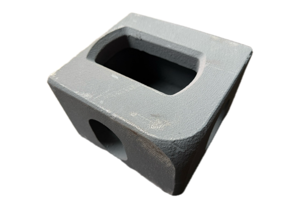


Other container news...

Obligation to Check Tightness When Selling a Reefer Container
Who is responsible for the refrigerant leak check when selling a refrigerated container? Find out what obligations the seller has at the time of handover and why they must provide a PTI report along with the technical data plate. Learn which regulatory requirements and F-gas record-keeping duties become the sole responsibility of the new owner.

New shipping containers
If you are currently considering purchasing a new shipping container, you are not alone. While just twenty years ago containers were used almost exclusively for maritime transport, today they have found their way into construction, storage, business, and even housing. This growing popularity brings with it a host of questions: Which type should you choose? How much does it cost? How do you recognize quality? How can you avoid falling victim to scammers?
New sea shipping containers
If you are currently considering purchasing a new shipping container, you are not alone. While just twenty years ago containers were used almost exclusively for maritime transport, today they have found their way into construction, storage, business, and even housing. This growing popularity brings with it a host of questions: Which type should you choose? How much does it cost? How do you recognize quality? How can you avoid falling victim to scammers?

6m shipping container
Are you thinking about buying a 6-meter shipping container but aren’t sure what to look for? You are not alone—this 20-foot container is the best-selling size on the Czech market, and the differences between various types, conditions, and prices can be significant. In this guide, you will find everything you need to know: from exact dimensions and a comparison of categories (such as “one-way,” refurbished, and “Cargo Worthy”) to current prices and shipping advice.