
The ISO corner casting standard
Every standardized shipping container on the planet — over 40 million of them — relies on exactly eight critical components to be lifted, stacked, secured, and transported across ships, trains, and trucks. Those components are the corner castings. And every single one of those corner castings is manufactured to a single international specification: the ISO corner casting standard, formally known as ISO 1161.
This standard is the invisible infrastructure behind global trade. A corner casting poured in a Chinese foundry must mate perfectly with a twistlock on a German chassis, a spreader in a Dutch port, and a securing system on a Panamanian-flagged vessel. Without ISO 1161, the intermodal container system would fracture into incompatible regional systems — and global logistics as we know it would cease to function.
What Is the ISO Corner Casting Standard?
Understanding ISO 1161 at a Glance
The ISO corner casting standard — properly designated ISO 1161:2016, Series 1 freight containers — Corner and intermediate fittings — Specifications — is an international standard published by the International Organization for Standardization that establishes the basic dimensions, functional requirements, and strength requirements for corner and intermediate fittings on Series 1 freight containers.
In plain terms, ISO 1161 defines exactly how the eight cast-steel blocks at the corners of a shipping container must be shaped, sized, positioned, and tested. The standard covers:
- Shape and basic dimensions of the casting body and all openings
- Position and orientation of the three apertures on each casting
- Functional requirements — how the casting must interface with twistlocks, spreaders, bridge clamps, and lashing systems
- Strength requirements — the specific forces (in kilonewtons) the casting must withstand without permanent deformation or fracture
- Marking requirements — permanent identification of manufacturer, heat number, and standard reference
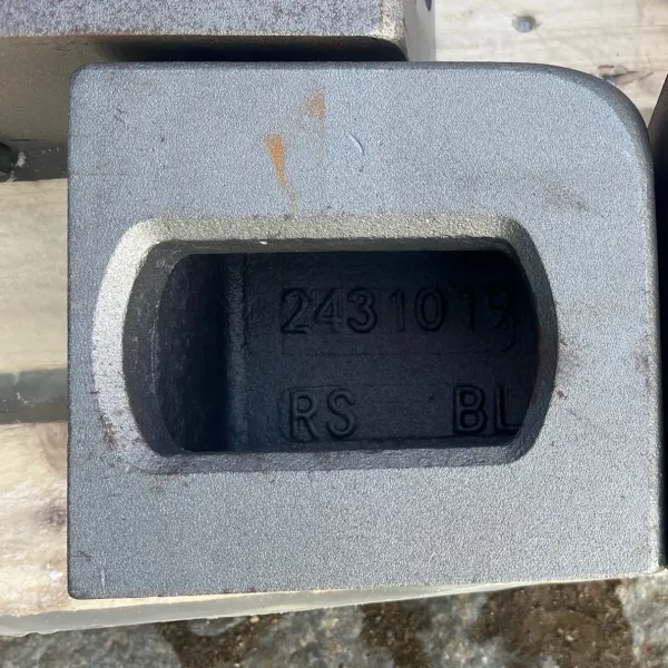
A single ISO-compliant corner casting block measures 178 mm in length, 162 mm in width, and 118 mm in height. It features three distinct openings: a stacking hole (circular, on the top or bottom face), a side hole (stadium/oval shape, on the long face), and a front hole (shield-shaped on top castings, oval on bottom castings). These three apertures serve as the universal connection points for every piece of container handling equipment in the global fleet.
Why Standardized Corner Castings Are Critical for Global Trade
The corner casting is the sole load-bearing interface between a shipping container and the equipment that moves it. When a crane lifts a fully laden 40-foot container — weighing up to 30,480 kg (67,200 lbs) — every single kilogram of that load travels through just four top corner castings. When nine containers are stacked in a vessel’s hold during heavy seas, the bottom castings endure compressive forces exceeding 848 kilonewtons (over 190,000 pounds-force).
Without the ISO corner casting standard, none of this would be interoperable. A container built in Shanghai must be liftable by a crane in Rotterdam, securable on a chassis in Chicago, and stackable beneath containers from a different manufacturer in Santos. The standard achieves this through precise dimensional tolerances — typically 0 to +1.5 mm — and rigorous strength testing protocols. The 1.5 mm tolerance window on the stacking hole diameter (approximately 97 to 99 mm) is especially critical: a hole that is too small will cause twistlocks to jam during crane operations, while one that is too large risks the lock disengaging mid-lift — a catastrophic failure mode.
Where Did the ISO Corner Casting Standard Come From?
From Malcom McLean to International Standardization
The story of the ISO corner casting standard begins not with a standards committee but with a truck driver from North Carolina. In 1956, Malcom McLean launched the first container ship — the converted tanker Ideal X — carrying 58 trailer bodies from Newark to Houston. McLean’s core insight was that cargo should move in a single box across ship, rail, and truck without being unpacked at each transfer point.
McLean’s early containers used corner posts with simple steel fittings, but the concept of a universal, standardized corner casting was still years away. The US military accelerated development during the Vietnam War through its “Conex” (Container Express) program, which required boxes that could be handled by different services’ equipment. Military specifications demanded standardized corner fittings, and this practical necessity pushed the commercial industry toward a common design.
By the late 1960s, the International Organization for Standardization had convened Technical Committee 104 (TC 104) — Freight Containers — to develop global standards. The first edition of ISO 1161 was published in 1984, establishing the corner casting as a truly international component. This was a landmark achievement: for the first time, a container corner casting manufactured anywhere in the world would fit equipment manufactured anywhere else.
The Evolution of ISO 1161: 1984 to 2016
The standard has undergone several revisions to keep pace with container industry evolution. Each revision refined existing requirements and added provisions for new container types.
| Edition | Year | Key Changes |
|---|---|---|
| ISO 1161:1984 | 1984 | Original standard. Established basic dimensions, hole profiles, and strength requirements for corner fittings on Series 1 containers. Defined the four position types: TL, TR, BL, BR. |
| ISO 1161:1990 | 1990 | Minor revision. Refined tolerance specifications and clarified testing methodology. |
| ISO 1161:2016 | 2016 | Current edition. Major update introducing intermediate fittings for containers longer than 40 feet (45ft, 48ft, 53ft). Added provisions for wider-body domestic and European containers. Updated marking requirements and strength testing protocols. |
The 2016 revision was particularly significant because it formally addressed the growing fleet of containers exceeding the classic 40-foot length. These longer containers — widely used in North American domestic intermodal service and increasingly in international trades — require additional corner fittings at the 40-foot position so they can be stacked atop standard 40-foot containers. ISO 1161:2016 codified the dimensional and strength requirements for these intermediate fittings, ensuring they work seamlessly with standard handling equipment despite being positioned on wider container bodies.
What Are the Standard ISO Corner Casting Dimensions and Specifications?
Core Dimensional Specifications
Every ISO 1161-compliant corner casting shares identical external envelope dimensions, regardless of position (top/bottom, left/right). This is the foundation of global interoperability.
| Parameter | Value (Metric) | Value (Imperial) |
|---|---|---|
| Length | 178 mm | 7.01 inches |
| Width | 162 mm | 6.38 inches |
| Height | 118 mm | 4.65 inches |
| Wall thickness (top plate) | ~20 mm minimum | ~0.79 inches |
| Wall thickness (general) | ~12.7 mm (3/4″) typical | 0.50 inches |
| Weight per unit (cast steel) | 10.5–12.5 kg | 23–28 lbs |
| Complete set weight (8 pcs) | 85–100 kg | 187–220 lbs |
The three apertures on each casting have distinct profiles:
- Stacking hole (top/bottom face): A circular opening with a nominal diameter refined by ISO 1161 to accept standard twistlock heads. The practical opening measures approximately 97–99 mm in diameter, with tight tolerances to prevent both jamming and disengagement.
- Side hole (long face): A stadium-shaped oval, approximately 65 mm × 130 mm, used primarily for horizontal connections such as bridge clamps, lashing bars, and inter-box connectors.
- Front hole (short/end face): On top castings, this is a shield-shaped (also called “acorn” or “pear-shaped”) opening — wider at the top, tapering downward — that guides crane spreader cones into position. On bottom castings, this is a uniform oval opening, since bottom castings do not need to guide spreaders.
Critical Tolerances and Why They Matter
The ISO corner casting standard does not merely specify nominal dimensions; it defines permissible tolerances that are the difference between safe operation and catastrophic failure. The general tolerance band for most critical dimensions is 0 to +1.5 mm — meaning the actual value can be up to 1.5 mm larger than nominal but never smaller.
Consider the stacking hole diameter. If the hole is undersized, a twistlock head that should rotate freely will bind. The crane operator feels resistance, applies more force, and potentially damages both the lock and the casting. Worse, the container might not seat properly, creating an unstable stack. If the hole is oversize beyond tolerance, the twistlock head has excessive play. Under dynamic loads at sea, the lock can vibrate, rotate, and potentially disengage — dropping the container from the stack.
Manufacturers verify these tolerances using Coordinate Measuring Machines (CMMs), which probe the casting at defined reference points and compare measurements against the ISO 1161 dimensional drawing. This is typically done on a sample basis from each production heat.
Hole Positions: The P and S Dimensions
Beyond the casting body itself, the most critical dimensional parameters are not about the casting block but about where the holes are positioned relative to the entire container. These are the P and S dimensions, which define the center-to-center distances between corner casting apertures.
| Dimension | Description | Standard Value (ISO Containers) |
|---|---|---|
| P (width) | Center-to-center distance across the container width | 2,259 mm (7 ft 4.94 in) |
| S (length, 20ft) | Center-to-center distance along the container length for 20ft units | 5,853 mm (19 ft 2.43 in) |
| S (length, 40ft) | Center-to-center distance along the container length for 40ft units | 11,985 mm (39 ft 3.85 in) |
| S (length, 45ft) | Center-to-center distance for 45ft containers (primary corners) | 13,716 mm (45 ft 0 in) |
The P dimension — 2,259 mm — is essentially universal across all ISO Series 1 containers. This is what makes a crane spreader manufactured for 8-foot-wide containers work with every standard container in the world. Even wider containers (pallet-wide, 8’6″ US domestic, 2.5 m European) maintain this same P dimension by offsetting the hole positions inward within slightly wider castings. The intermediate fittings on 45ft, 48ft, and 53ft containers at the 40-foot position also maintain the 2,259 mm P dimension so they can stack under standard 40-foot units.
What Are the Four Types of Corner Castings (TL, TR, BL, BR)?
Position-Based Classification
ISO 1161 defines exactly four types of corner castings, each used twice on a standard container. The designations are positional abbreviations:
- TL — Top Left: Upper corner, left side (when facing the container door or front wall)
- TR — Top Right: Upper corner, right side
- BL — Bottom Left: Lower corner, left side
- BR — Bottom Right: Lower corner, right side
The “left” and “right” convention always assumes the observer is standing outside the container, looking directly at either the door end or the front wall. Left and right variants are mirror images of each other — a TL casting is the mirror of a TR casting, and a BL is the mirror of a BR. This mirror symmetry is why every container requires exactly two of each type: one for each side.
To help identify castings during inspection, repair, or assembly, each piece carries an internal relief mark — “TL,” “TR,” “BL,” or “BR” — cast directly into the metal during manufacturing. This marking is visible on the inside face of the casting, the surface that faces the container interior.
The CC-1 to CC-4 Manufacturer Numbering System
In spare parts catalogs, e-commerce platforms, and manufacturer datasheets, you will increasingly encounter the designations CC-1, CC-2, CC-3, and CC-4. These are not part of the ISO 1161 standard — they are internal catalog codes created by manufacturers and distributors to simplify ordering.
Important: The mapping of CC-1 through CC-4 to specific ISO positions (TL/TR/BL/BR) is not universally standardized. Different suppliers may use different mappings. Always verify with the specific vendor before ordering.
That said, the most commonly encountered mapping — particularly from European and Asian suppliers — follows a clockwise convention:
| Catalog Designation | ISO 1161 Position | Description |
|---|---|---|
| CC-1 | TL — Top Left | Upper left corner |
| CC-2 | TR — Top Right | Upper right corner |
| CC-3 | BL — Bottom Left | Lower left corner |
| CC-4 | BR — Bottom Right | Lower right corner |
Some manufacturers use an alternative system that embeds the ISO designation directly in the code: CCTL, CCTR, CCBL, CCBR. Others, such as JOST, use completely different numerical series (CC 299, CC 300, etc.) that reference specific product variants rather than basic positions. The key takeaway is that the ISO standard itself recognizes only TL, TR, BL, and BR — and any CC-number system is merely a commercial overlay.
A complete set for one container consists of 8 pieces: 2× TL, 2× TR, 2× BL, 2× BR (or 2× CC-1 through 2× CC-4). For partial work — such as repairing one end of a container — a “half set” of 4 pieces (one of each type) is available.
What Is the Difference Between Top and Bottom Corner Castings?
Top Corner Castings (TL, TR): Anatomy and Function
Top corner castings are designed primarily for lifting and vertical load transfer. Their three openings serve distinct purposes:
- Stacking hole (top face, faces upward): This is the primary load-bearing aperture. When a crane spreader engages the container, its twistlock cones insert into these four top holes and lock. When containers are stacked, the bottom stacking holes of the upper container seat onto the top stacking holes of the lower container. All vertical forces — both lifting tension and stacking compression — pass through these holes.
- Side hole (stadium-shaped oval, faces the container side wall): Used for horizontal connections, such as bridge fittings that connect two adjacent containers side-by-side on a vessel. Also used for lashing bars that secure containers against tipping.
- Front hole (shield/acorn-shaped, faces the container end): The distinctive shield shape — wider at the top, tapering toward the bottom — serves as a guidance feature for crane spreader cones. During a lift, the spreader descends toward the container. If misaligned, the cone contacts the sloped edges of the shield hole and is guided into proper position. This self-centering mechanism allows crane operators to pick containers even in windy conditions or imperfect alignment.
Bottom Corner Castings (BL, BR): Anatomy and Function
Bottom corner castings are designed primarily for securing and load transfer to supporting surfaces. Their configuration differs from top castings in one key respect:
- Stacking hole (bottom face, faces downward): Interfaces with twistlocks on a truck chassis, railcar, vessel deck, or the top castings of a container below. When the container is at rest on a chassis, the entire load passes through these four holes onto the chassis twistlocks.
- Side hole (stadium-shaped oval): Identical function to top castings — horizontal connections and lashing.
- Front hole (uniform oval, NOT shield-shaped): This is the distinguishing feature between top and bottom castings. Bottom castings use a simple oval front hole rather than a shield shape. Since bottom castings are never engaged by crane spreaders, there is no need for the guidance taper. The oval shape is simpler to manufacture and equally functional for the bottom casting’s role: lashing connections and chassis securing.
Side-by-Side Comparison
| Feature | Top Casting (TL, TR) | Bottom Casting (BL, BR) |
|---|---|---|
| Stacking hole orientation | Faces upward | Faces downward |
| Front hole shape | Shield/acorn-shaped (tapered guidance) | Uniform oval |
| Primary function | Lifting interface, stacking load transfer | Securing to chassis/deck, lower stacking interface |
| Spreader engagement | Yes — shield hole guides spreader cone | No |
| Internal relief marking | TL or TR | BL or BR |
| Critical inspection points | Deformation around top hole, shield hole cracking | Deformation around bottom hole, oval hole elongation |
What Materials Are ISO Corner Castings Made From?
Cast Steel: The Industry Standard (SCW480 / ASTM A148)
Over 99% of ISO corner castings are manufactured from low-alloy cast steel. The most common grade designation is SCW480 (common in Asian and European manufacturing), which is functionally equivalent to grades specified under ASTM A148 for structural steel castings.
The chemical composition is tightly controlled, not primarily for strength but for weldability. Corner castings must be welded to the container’s corner posts and top/bottom side rails during assembly — typically to Corten steel (high-strength, low-alloy, weathering steel). If the casting material has too high a carbon content or the wrong alloy balance, the weld will crack in the heat-affected zone (HAZ).
| Element | Typical Content (%) | Purpose |
|---|---|---|
| Carbon (C) | 0.20–0.30% max (often ≤0.20%) | Strength; kept low for weldability |
| Manganese (Mn) | 0.60–1.00% | Deoxidizer, strength, toughness |
| Silicon (Si) | 0.30–0.60% | Deoxidizer, casting fluidity |
| Phosphorus (P) | ≤0.04% | Impurity control (brittleness) |
| Sulfur (S) | ≤0.04% | Impurity control (hot shortness) |
The low carbon content — typically capped at 0.20%, well below the 0.30% threshold where weldability degrades — is non-negotiable. A casting with carbon at 0.40% would fail the Charpy V-notch impact test at -20°C, making it unsuitable for containers operating in cold climates. The manganese and silicon serve primarily as deoxidizers during the casting process, ensuring a clean, pore-free structure.
The heat treatment sequence is equally critical. After casting, all corner castings must undergo normalizing — heating to approximately 900°C followed by air cooling — to refine the grain structure and relieve internal stresses from the casting process. Some manufacturers add a tempering step for enhanced toughness. Castings that skip or botch the normalizing cycle exhibit brittle fracture behavior: they crack at corner radii under load without prior visible deformation, a dangerous failure mode in service.
Stainless Steel and Aluminum Alternatives
While cast steel dominates, two alternative materials serve specialized applications:
Stainless steel corner castings are used primarily on tank containers and bulker containers carrying corrosive cargo. The stainless construction resists chemical attack from spills and washdown operations. They are also specified for food-grade containers where surface contamination risks must be eliminated. Stainless castings are approximately 40–50% more expensive than cast steel and require specialized welding procedures.
Aluminum corner castings appear on lightweight military containers, offshore containers, and some airfreight-compatible units. The weight savings are significant — an aluminum casting weighs roughly 4–5 kg versus 11–12 kg for steel — reducing the container’s tare weight by approximately 55 kg across eight castings. However, aluminum castings have lower strength, are more expensive, and require more careful handling to avoid thread damage in twistlock interfaces.
| Property | Cast Steel (SCW480) | Stainless Steel | Aluminum Alloy |
|---|---|---|---|
| Weight per unit | 10.5–12.5 kg | 11–13 kg | 4–5 kg |
| Tensile strength | ~480 MPa | ~500–600 MPa | ~250–300 MPa |
| Weldability to Corten | Excellent | Requires special procedure | Incompatible |
| Corrosion resistance | Moderate (paints required) | Excellent | Good |
| Cost (relative) | 1× (baseline) | 3–4× | 2–3× |
| Typical application | All standard dry containers | Tank, bulker, food-grade | Military, offshore, airfreight |
How Are Corner Castings Manufactured and Certified?
The Manufacturing Process: From Sand Mold to Finished Product
The production of an ISO-compliant corner casting follows a tightly controlled sequence, typically at foundries specializing in steel castings for the container industry:
- Pattern making and molding: A pattern — an exact replica of the finished casting with shrinkage allowance built in — is used to create a sand mold. Most corner castings are produced using green sand molding or chemically bonded sand molding. The mold incorporates cores to form the three hollow apertures.
- Melting and pouring: The steel charge — carefully weighed to achieve the target SCW480 chemistry — is melted in an electric arc or induction furnace at approximately 1,550–1,600°C. Pouring temperature and speed are critical: too fast and sand inclusions form; too slow and the steel solidifies prematurely, causing cold shuts.
- Shakeout and fettling: After cooling, the casting is shaken out of the sand mold. Risers and gates — the channels through which molten steel entered the mold — are cut off. Surfaces are ground to remove burrs, sharp edges, and any flash that could damage twistlock engagement.
- Heat treatment: The castings undergo normalizing (900°C, air cool) and optionally tempering. This step transforms the as-cast dendritic structure into a uniform, fine-grained microstructure with the required balance of strength and toughness.
- Shot blasting: Steel shot is propelled at high velocity against the casting surface. This removes residual sand, scale from heat treatment, and produces a uniform surface profile ideal for paint adhesion.
- Machining and dimensional verification: Critical surfaces — particularly the stacking hole rim — may receive a light machining pass. Samples from each production batch are inspected on a CMM against the ISO 1161 dimensional drawing.
Strength Testing and Certification Requirements
The ISO corner casting standard mandates specific destructive and non-destructive testing protocols. These tests are not merely “the casting should be strong” — they specify exact force values that must be withstood without permanent deformation beyond defined limits.
The two most demanding tests are:
Top Lift Test: A vertical tensile force of 150 kN (approximately 33,700 lbf) is applied through the top stacking holes, simulating a crane lifting a fully laden container. The casting must withstand this force without cracking and with no permanent deformation exceeding the ISO 1161 limit.
Stacking Test: A compressive force of 848 kN (approximately 190,600 lbf) is applied vertically, simulating a container stacked six-high in a fully laden condition under heavy sea motion. This is the worst-case stacking scenario and represents forces far exceeding static weight alone — the dynamic amplification from vessel rolling and pitching multiplies the static load significantly.
Additional tests include:
- Charpy V-notch impact test at -20°C: Verifies that the material remains ductile (not brittle) at low temperatures. A minimum absorbed energy is specified.
- Restraint/lashing test: Horizontal forces applied through side and front holes, simulating the loads imposed by lashing systems during sea transport.
In our industry’s destructive testing records, three failure modes are commonly documented:
- Brittle fracture — caused by improper heat treatment. The casting breaks at a corner radius without visible prior deformation.
- Ductile yielding — caused by material that is too soft. The hole elongates beyond tolerance, causing twistlock disengagement even though the casting has not cracked.
- Weld HAZ cracking — caused by high carbon equivalent in the casting material. Cracks initiate at the weld heat-affected zone between the casting and the container rail.
Certification Bodies: ABS, DNV, Lloyds Register
Every certified corner casting must carry a permanent mark cast into its surface during manufacturing. This mark identifies:
- Manufacturer identification (logo or code)
- Heat number (traceability to the specific batch of steel)
- Standard reference (“ISO 1161”)
These markings enable traceability from the field back to the foundry. If a casting fails in service, the heat number allows investigators to locate the exact material certificate, chemical analysis, and test records for that batch.
Major classification societies — American Bureau of Shipping (ABS), DNV, Lloyds Register, Bureau Veritas — provide type approval and production certification for corner castings. A casting that carries ABS certification has passed the society’s type testing and periodic audit program. For containers operating under the International Convention for Safe Containers (CSC), the corner castings are a critical element of the container’s overall safety approval.
How Do ISO 1161, ISO 668, and Other Standards Work Together?
The ISO Standards Ecosystem for Freight Containers
ISO 1161 does not operate in isolation. It is one component of an interconnected family of ISO standards that collectively define every aspect of a shipping container. Understanding how these standards relate is essential for anyone working in container design, repair, or procurement.
| ISO Standard | Scope | Relationship to ISO 1161 |
|---|---|---|
| ISO 1161 | Corner and intermediate fittings — dimensions, function, strength | The standard this article covers |
| ISO 668 | External dimensions and maximum gross mass of Series 1 containers | Defines the container envelope; ISO 1161 castings must sit within this envelope and match the corner geometry |
| ISO 1496 | Specifications and testing of Series 1 containers (multiple parts) | Defines the overall container strength tests; relies on ISO 1161 castings as the load application points |
| ISO 6346 | Container classification codes and identification markings | References ISO 1161 castings as part of the container ID system; the CSC plate is often mounted near a casting |
| ISO 830 | Freight containers — vocabulary and terminology | Provides the formal definitions for “corner fitting,” “corner casting,” and related terms used in ISO 1161 |
A useful analogy: if ISO 668 defines the “box” and its size classes, ISO 1161 defines the “handles” on the box. Both standards must work together. A container whose corner post welding distorts the casting position may have castings that individually meet ISO 1161 but fail the overall container corner diagonal tolerance specified in ISO 668. Manufacturers use robust jigs and fixtures to control this distortion during assembly.
ISO 1161 vs BS 3951 vs Lloyds Register Guidance Note A
For historical and practical reasons, you may encounter references to standards other than ISO 1161:
- BS 3951 is the British Standard equivalent of ISO 1161. Historically, BS 3951 pre-dated ISO 1161 in some respects and served as the basis for early container corner fitting specifications in the UK and Commonwealth markets. Today, BS 3951 is essentially superseded by ISO 1161, but legacy references persist in older documentation and some national regulations.
- Lloyds Register Guidance Note A provides additional requirements specifically for offshore containers — containers used on oil and gas platforms, which face more severe dynamic loading, corrosive environments, and stricter safety regimes than standard intermodal containers. LR GN A incorporates ISO 1161 by reference but adds supplementary requirements for casting inspection frequency, material certification, and allowable defect limits.
In practice, for any standard intermodal container, ISO 1161 is the governing document. Offshore containers, military units, and some specialized equipment may also require compliance with supplementary classification society rules.
What Are Intermediate Corner Fittings and When Are They Used?
Beyond the Eight Corners: Intermediate Fittings for Extended Containers
A standard 20-foot or 40-foot container has exactly eight corner castings. But containers longer than 40 feet — specifically 45-foot, 48-foot, and 53-foot units — present a structural and operational challenge. A 53-foot container cannot be stacked directly on top of two 20-foot containers because the corner casting positions do not align. Yet these longer containers must still be stackable on standard 40-foot containers beneath them and under standard 20-foot or 40-foot units above them.
The solution is intermediate corner fittings — additional castings positioned along the bottom side rails at precisely the 40-foot position. A 45-foot container, for example, has:
- 8 primary corner castings at its four corners (standard TL, TR, BL, BR positions at the 45-foot length)
- 8 intermediate fittings at the 40-foot position (four on the bottom side rails, four on the top side rails)
These intermediate fittings allow the 45-foot container to sit on a 40-foot chassis twistlock pattern and to be stacked on top of a 40-foot container below. The intermediate fittings on the top side rails allow a 40-foot or shorter container to be stacked above.
ISO 1161:2016 was the first edition to formally define the specifications for these intermediate fittings, including their dimensional requirements, hole profiles, and strength testing protocols.
USA Inland vs European Wide-Body Castings
Not all containers use the standard 8-foot (2,438 mm) width. Two important non-standard widths drive specialized corner casting designs:
USA Inland (Domestic) Containers — 8’6″ (2,591 mm) wide: Common in North American intermodal service, particularly for 48-foot and 53-foot units. These containers are 153 mm (6 inches) wider than ISO standard containers. To maintain the critical P dimension of 2,259 mm — ensuring compatibility with standard spreaders and chassis — the corner castings on these wider containers have their holes offset inward by approximately 76 mm per side. The casting body itself is slightly wider, but the hole positions conform to the universal P dimension.
European Swap Bodies and Pallet-Wide Containers — 2,500 mm or 2,550 mm wide: Designed to accommodate two standard European pallets (1,200 mm × 800 mm) side by side. Like USA inland units, these wider containers use specialized castings with inward-offset holes to maintain the 2,259 mm P dimension. European swap bodies may also use different casting types altogether, including fittings designed for grapple-arm handling systems rather than twistlock spreaders.
How Are Corner Castings Inspected, and When Must They Be Replaced?
IICL Inspection Criteria for Corner Castings
The Institute of International Container Lessors (IICL) publishes the definitive inspection and repair standards for the global container fleet. IICL Guide for Container Equipment Inspection and the IICL Repair Manual for Steel Freight Containers establish clear criteria for what constitutes acceptable wear and what requires repair or replacement.
For corner castings specifically, the following conditions typically require action:
- Deformation exceeding specified limits: Any visible deformation around the stacking hole, side hole, or front hole that exceeds the IICL’s dimensional thresholds requires replacement. Even slight elongation of the stacking hole can compromise twistlock security.
- Cracks of any length: Cracks radiating from hole corners are considered critical defects. Corner casting cracks propagate under cyclic loading and can lead to sudden, catastrophic failure. The IICL standard does not permit cosmetic acceptance of any crack in a corner casting.
- Corrosion exceeding depth limits: While surface rust is acceptable, pitting corrosion that reduces the effective wall thickness below the structural minimum requires replacement. This is particularly relevant for containers operating in marine environments.
- Weld separation between casting and container structure: The weld connecting the corner casting to the corner post or rail must be intact. A cracked or separated weld redistributes load in ways the design does not anticipate.
Inspection frequency under normal operations is a minimum of once every 60 days, though many fleet operators inspect at every interchange — each time a container is transferred between parties.
Repair or Replace? Why Welding Repairs on Castings Are Prohibited
A critical rule in container maintenance: corner castings cannot be repaired by welding. This prohibition exists in the IICL standards, ISO 1161, and the requirements of all major classification societies.
The reasoning is metallurgical. A corner casting achieves its specified mechanical properties — particularly its toughness and ductility — through controlled heat treatment (normalizing and tempering). Applying a welding torch to repair a crack or fill a worn surface introduces intense, localized heat that:
- Creates a new heat-affected zone (HAZ) with altered microstructure adjacent to the weld, prone to cracking
- Tempers or over-tempers previously heat-treated material, reducing strength
- Introduces residual stresses from differential heating and cooling that can initiate new cracks
- Cannot restore the original grain structure across the repaired area
The only acceptable corrective action for a damaged corner casting is complete replacement. The replacement procedure involves:
- Cutting out the damaged casting, preserving the original corner post and rail ends
- Preparing the joint faces for full-penetration welding
- Fitting the new certified casting, ensuring proper alignment with the P and S dimensional requirements
- Welding to the container structure using qualified procedures and approved filler materials
- Post-weld inspection (visual, dye penetrant, or magnetic particle testing of the weld)
CSC Certification and Ongoing Compliance
Under the International Convention for Safe Containers (CSC), every container used in international transport must carry a valid CSC Safety Approval Plate. Corner castings are an integral part of the container structure covered by this approval. During periodic CSC examinations — required at intervals not exceeding 30 months under the standard scheme, or more frequently under the Approved Continuous Examination Program (ACEP) — the corner castings are inspected for compliance with the original approved design.
If a corner casting is replaced, the repair must be documented, and the replacement casting must carry the required permanent markings (manufacturer, heat number, ISO 1161 reference). The CSC plate is not re-issued solely for a casting replacement, but the repair must be recorded in the container’s maintenance history.
How Do You Select the Right Corner Casting for Your Application?
Decision Framework for Buyers
Whether you are repairing a container, building a container-based structure, or procuring castings for manufacturing, selecting the right corner casting requires answering a sequence of questions:
- What is the container width?
- 8 feet (2,438 mm): Standard ISO 1161 corner casting — the universal default
- 8 feet 6 inches (2,591 mm): USA inland/domestic casting with inward-offset holes
- 2,500 mm or 2,550 mm: European pallet-wide or swap body casting with inward-offset holes
- What material is required?
- Standard dry container, general use: Cast steel (SCW480 or equivalent)
- Tank/bulker/food-grade container: Stainless steel
- Military, offshore, weight-critical application: Aluminum alloy
- What certification level is needed?
- Standard intermodal container repair: Certified to ISO 1161 with manufacturer markings
- CSC-governed container: Must have full traceability (manufacturer, heat number, standard reference)
- Offshore container: May require additional classification society approval (ABS, DNV, LR)
- Is this for shipping use or stationary/conversion use?
- Shipping (lifting, stacking, transport): Must use fully certified, ISO 1161-compliant castings
- Stationary conversion (container home, office, storage): Certified castings are still recommended if the container will ever be lifted or moved, even by crane during installation
Common Ordering Pitfalls to Avoid
Based on real-world procurement experience, the most common mistakes when ordering corner castings include:
- Assuming CC-1/CC-2/CC-3/CC-4 mapping is universal. As discussed earlier, different suppliers use different numbering systems. Always confirm the mapping to TL/TR/BL/BR before placing an order. Ask the vendor directly: “Does your CC-1 correspond to ISO Top Left?”
- Overlooking the hole offset. For wider containers, the casting holes are offset inward by 28 mm, 55 mm, or more from the standard position. Ordering standard castings for a wide-body container will result in a P dimension mismatch.
- Mixing material types. A stainless steel casting cannot be welded to Corten steel corner posts with standard procedures. If the rest of the container is Corten/standard steel, the casting must be compatible.
- Ordering individual pieces without understanding the set logic. One container needs two of each type (TL, TR, BL, BR). A “half set” of 4 typically supplies one of each type — enough for one end of the container. Ensure you understand whether you are buying individual pieces or a set.
- Ignoring surface condition. Raw (uncoated) castings weld better than painted ones. If your application requires a corrosion-resistant finish, confirm whether the casting comes primed, painted, or uncoated.
What Does the Future Hold for Corner Casting Technology?
Smart Castings: RFID and IoT Integration
The corner casting — long the most low-tech yet critical component on a container — is becoming “smart.” Several technology trends are converging:
RFID-tagged castings embed a radio-frequency identification chip within or on the casting body. When a container passes through a gate equipped with RFID readers, the tag transmits the container’s identity without requiring line-of-sight to the painted markings. This enables automated gate processing at terminals, reducing truck turnaround times from minutes to seconds.
Load-sensing castings integrate strain gauges or fiber-optic sensors into the casting structure to measure real-time loads during lifting, stacking, and transport. This data can alert fleet managers to overloading, detect improper stacking, and provide evidence in damage claims. Some prototypes can transmit load data via low-power wide-area networks (LPWAN) to cloud-based fleet management platforms.
While these smart casting technologies remain niche as of 2026, their adoption is accelerating as container shipping lines and leasing companies seek to reduce inspection costs and improve utilization rates.
Advanced Materials and Manufacturing
The foundry industry is not standing still. Emerging trends include:
- 3D-printed sand molds and cores: Additive manufacturing of mold components allows complex internal geometries that improve casting quality while reducing weight. One manufacturer has demonstrated a corner casting with an optimized internal rib structure — produced using 3D-printed molds — that weighs 15% less than a conventional design while meeting all ISO 1161 strength requirements.
- Higher-strength cast steel grades: Development of micro-alloyed cast steels with improved strength-to-weight ratios could enable lighter castings without sacrificing load capacity. These grades use small additions of vanadium, niobium, or titanium to achieve precipitation hardening during the normalizing cycle.
- Improved corrosion-resistant alloys: For containers operating in highly corrosive environments — chemical tank containers, offshore units, Arctic vessels using de-icing salts — new stainless steel formulations offer better pitting resistance and longer service life.
The ISO corner casting standard will continue to evolve. Future revisions may incorporate provisions for smart technologies, recognize new materials, and address the specific demands of automated container handling systems in increasingly autonomous terminals. But the fundamental principle — that eight standardized steel blocks make the entire global container system work — will remain unchanged.
Frequently Asked Questions
What does ISO 1161 specify?
ISO 1161 specifies the basic dimensions, functional requirements, and strength requirements for corner and intermediate fittings on Series 1 freight containers. It defines the shape and size of the casting body, the position and orientation of the three apertures on each casting, the forces the casting must withstand, and the permanent markings required for traceability. The standard ensures that a corner casting manufactured anywhere in the world will interface correctly with twistlocks, crane spreaders, and securing systems everywhere.
How many corner castings does a shipping container have?
A standard ISO shipping container has eight corner castings — four at the top corners and four at the bottom corners. Containers longer than 40 feet (45ft, 48ft, 53ft) have an additional eight intermediate fittings at the 40-foot position, for a total of 16 castings.
What are the standard ISO 1161 corner casting dimensions?
The standard external dimensions of an ISO 1161 corner casting are 178 mm (length) × 162 mm (width) × 118 mm (height). In imperial units, this is approximately 7.01 × 6.38 × 4.65 inches. Wall thickness is typically 12.7 mm (3/4 inch), with the top plate being thicker at approximately 20 mm minimum. Each cast steel unit weighs between 10.5 and 12.5 kg (23–28 lbs).
What are the four types of corner castings?
The four types, defined by position, are TL (Top Left), TR (Top Right), BL (Bottom Left), and BR (Bottom Right). “Left” and “right” are determined by viewing the container from the outside, facing the door or front wall. TL and TR are mirror images of each other, as are BL and BR. A standard container uses exactly two of each type.
What is the difference between ISO 1161 and ISO 668?
ISO 1161 governs the corner and intermediate fittings — their dimensions, hole profiles, strength requirements, and marking. ISO 668 governs the external dimensions and maximum gross mass ratings of the container itself — its length, width, height, and weight limits. The two standards work together: ISO 668 defines the box, ISO 1161 defines the handles.
What material are corner castings made from?
The overwhelming majority of corner castings are made from cast steel, specifically the SCW480 grade (or ASTM A148 equivalent), a low-alloy steel with tightly controlled carbon content (≤0.20%) for weldability. Alternative materials include stainless steel (for tank and food-grade containers) and aluminum alloy (for lightweight military and offshore containers).
How much does a corner casting weigh?
A single cast steel corner casting weighs approximately 10.5 to 12.5 kg (23 to 28 lbs), depending on the manufacturer and exact wall thickness. A complete set of eight castings weighs between 85 and 100 kg (187–220 lbs). Aluminum corner castings weigh approximately 4–5 kg (9–11 lbs) each.
What are the P and S dimensions for corner castings?
The P dimension (width center-to-center between casting holes) is 2,259 mm (7 ft 4.94 in) for all standard ISO containers. The S dimension (length center-to-center) is 5,853 mm (19 ft 2.43 in) for 20-foot containers and 11,985 mm (39 ft 3.85 in) for 40-foot containers. These dimensions are critical for spreader and chassis compatibility.
What are CC-1, CC-2, CC-3, and CC-4?
These are manufacturer catalog designations, not part of the ISO 1161 standard itself. In the most common mapping, CC-1 = TL (Top Left), CC-2 = TR (Top Right), CC-3 = BL (Bottom Left), and CC-4 = BR (Bottom Right). However, this mapping is not universal. Always verify with the specific supplier before ordering.
Can a damaged corner casting be repaired?
No. Welding repairs on corner castings are prohibited by IICL standards, ISO 1161, and classification society rules. The heat from welding alters the casting’s heat-treated microstructure, creating brittle zones and residual stresses that can lead to catastrophic failure. The only acceptable corrective action for a damaged corner casting is complete replacement with a certified, properly marked unit.
What strength tests are required for corner castings?
ISO 1161 mandates a top lift test (150 kN tensile force applied through the top stacking holes) and a stacking test (848 kN compressive force, simulating six-high laden stacking). Additional tests include a Charpy V-notch impact test at -20°C (verifying low-temperature ductility) and restraint/lashing tests applying horizontal forces through the side and front holes.
Are all corner castings the same?
No. While all ISO 1161-compliant standard castings share the same external envelope dimensions, they differ by position (Top Left vs Bottom Right, etc.), front hole shape (shield-shaped on top castings, oval on bottom castings), and stacking hole orientation (upward on top, downward on bottom). Additionally, specialized castings exist for wide-body USA domestic containers, European pallet-wide containers, and different materials (steel, stainless, aluminum).

 Czech Republic
 DELIVERY TO ADDRESS


